- 您现在的位置:买卖IC网 > Sheet目录3836 > PIC16C765-I/P (Microchip Technology)IC MCU OTP 8KX14 USB 40DIP
2000 Microchip Technology Inc.
Preliminary
DS41124C-page 101
PIC16C745/765
13.2.5
EXTERNAL CLOCK IN
In EC mode, users may directly drive the PIC16C745/
765 provided that this external clock source meets the
AC/DC timing requirements listed in Section 17.4.
Figure 13-2 below shows how an external clock circuit
should be configured.
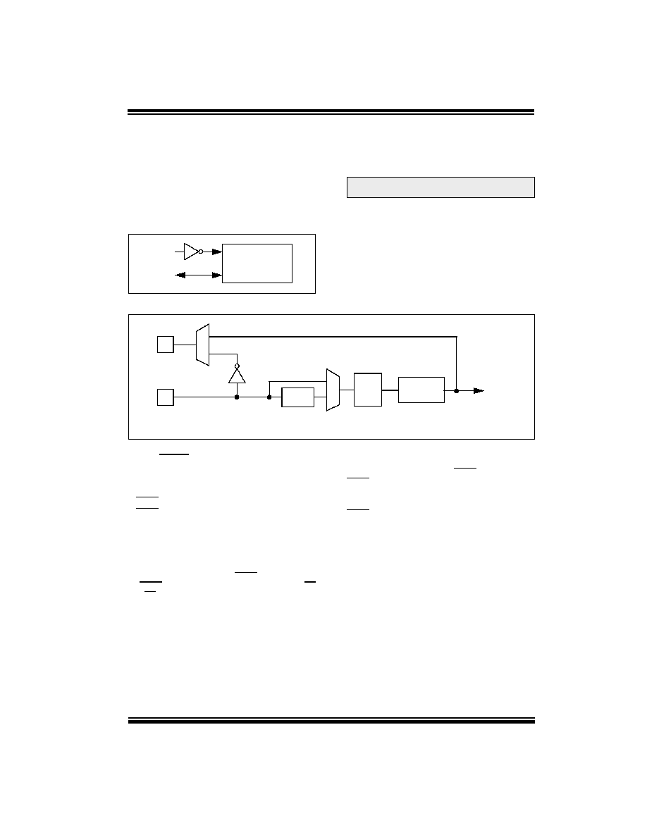
FIGURE 13-2: EXTERNAL CLOCK INPUT
OPERATION (EC OSC
CONFIGURATION)
13.2.6
E4 MODE
In E4 mode, a PLL module is switched on in-line with
the clock provided to OSC1. The output of the PLL
drives FINT.
FIGURE 13-3: OSCILLATOR/PLL CLOCK CONTROL
13.3
RESET
The PIC16CXX differentiates between various kinds of
RESET:
Power-on Reset (POR)
MCLR Reset during normal operation
MCLR Reset during SLEEP
WDT Reset (normal operation)
Brown-out Reset (BOR)
Some registers are not affected in any RESET condi-
tion; their status is unknown on POR and unchanged in
any other RESET. Most other registers are reset to a
“RESET state” on POR, on the MCLR and WDT Reset,
on MCLR Reset during SLEEP, and on BOR. The TO
and PD bits are set or cleared differently in different
RESET situations as indicated in Table 13-4. These
bits are used in software to determine the nature of the
RESET. See Table 13-7 for a full description of RESET
states of all registers.
A simplified block diagram of the on-chip RESET circuit
is shown in Figure 13-4.
The PICmicro devices have a MCLR noise filter in the
MCLR Reset path. The filter will detect and ignore
small pulses.
It should be noted that a WDT Reset does not drive
MCLR pin low.
Clock from
ext. system
PIC16C745/765
OSC1
OSC2/CLKOUT
CLKOUT
Note: CLKOUT is the same frequency as OSC1 if
in E4 mode, otherwise CLKOUT = OSC1/4.
OSC2
OSC1
EC
E4
HS
H4
4x PLL
6 MHz
Q Clock
Generator
To Circuits
24 MHz
FINT
EC
E4
HS
H4
745cov.book Page 101 Wednesday, August 2, 2000 8:24 AM
发布紧急采购,3分钟左右您将得到回复。
相关PDF资料
PIC16LF84A-04I/P
IC MCU FLASH 1KX14 EE 18DIP
PIC16C65B-20/P
IC MCU OTP 4KX14 PWM 40DIP
PIC18F2331-I/SO
IC PIC MCU FLASH 4KX16 28SOIC
PIC18LF4420-I/PT
IC MCU FLASH 8KX16 44TQFP
DSPIC33FJ64GP202-I/MM
IC DSPIC MCU/DSP 64K 28-QFN
PIC16C57-XT/SO
IC MCU OTP 2KX12 28SOIC
172061-3
DRAWER CONN 12P MALE
223041-4
FB-5R,VERTICAL SHROUD,120 POS
相关代理商/技术参数
PIC16C765-I/P
制造商:Microchip Technology Inc 功能描述:IC 8BIT CMOS MCU 16C765 DIP40
PIC16C765-I/PT
功能描述:8位微控制器 -MCU 14KB 256 RAM 33 I/O RoHS:否 制造商:Silicon Labs 核心:8051 处理器系列:C8051F39x 数据总线宽度:8 bit 最大时钟频率:50 MHz 程序存储器大小:16 KB 数据 RAM 大小:1 KB 片上 ADC:Yes 工作电源电压:1.8 V to 3.6 V 工作温度范围:- 40 C to + 105 C 封装 / 箱体:QFN-20 安装风格:SMD/SMT
PIC16C765T-I/L
功能描述:8位微控制器 -MCU 14KB 256 RAM 33 I/O RoHS:否 制造商:Silicon Labs 核心:8051 处理器系列:C8051F39x 数据总线宽度:8 bit 最大时钟频率:50 MHz 程序存储器大小:16 KB 数据 RAM 大小:1 KB 片上 ADC:Yes 工作电源电压:1.8 V to 3.6 V 工作温度范围:- 40 C to + 105 C 封装 / 箱体:QFN-20 安装风格:SMD/SMT
PIC16C765T-I/PT
功能描述:8位微控制器 -MCU 14KB 256 RAM 33 I/O RoHS:否 制造商:Silicon Labs 核心:8051 处理器系列:C8051F39x 数据总线宽度:8 bit 最大时钟频率:50 MHz 程序存储器大小:16 KB 数据 RAM 大小:1 KB 片上 ADC:Yes 工作电源电压:1.8 V to 3.6 V 工作温度范围:- 40 C to + 105 C 封装 / 箱体:QFN-20 安装风格:SMD/SMT
PIC16C76T-04/SO
功能描述:8位微控制器 -MCU 14KB 368 RAM 22 I/O RoHS:否 制造商:Silicon Labs 核心:8051 处理器系列:C8051F39x 数据总线宽度:8 bit 最大时钟频率:50 MHz 程序存储器大小:16 KB 数据 RAM 大小:1 KB 片上 ADC:Yes 工作电源电压:1.8 V to 3.6 V 工作温度范围:- 40 C to + 105 C 封装 / 箱体:QFN-20 安装风格:SMD/SMT
PIC16C76T-04E/SO
功能描述:8位微控制器 -MCU 14KB 368 RAM 22 I/O RoHS:否 制造商:Silicon Labs 核心:8051 处理器系列:C8051F39x 数据总线宽度:8 bit 最大时钟频率:50 MHz 程序存储器大小:16 KB 数据 RAM 大小:1 KB 片上 ADC:Yes 工作电源电压:1.8 V to 3.6 V 工作温度范围:- 40 C to + 105 C 封装 / 箱体:QFN-20 安装风格:SMD/SMT
PIC16C76T-04I/SO
功能描述:8位微控制器 -MCU 14KB 368 RAM 22 I/O RoHS:否 制造商:Silicon Labs 核心:8051 处理器系列:C8051F39x 数据总线宽度:8 bit 最大时钟频率:50 MHz 程序存储器大小:16 KB 数据 RAM 大小:1 KB 片上 ADC:Yes 工作电源电压:1.8 V to 3.6 V 工作温度范围:- 40 C to + 105 C 封装 / 箱体:QFN-20 安装风格:SMD/SMT
PIC16C76T-10/SO
功能描述:8位微控制器 -MCU 14KB 368 RAM 22 I/O RoHS:否 制造商:Silicon Labs 核心:8051 处理器系列:C8051F39x 数据总线宽度:8 bit 最大时钟频率:50 MHz 程序存储器大小:16 KB 数据 RAM 大小:1 KB 片上 ADC:Yes 工作电源电压:1.8 V to 3.6 V 工作温度范围:- 40 C to + 105 C 封装 / 箱体:QFN-20 安装风格:SMD/SMT